|
Tutorials |
|
|
|

Embedded Systems 620.220
Laboratory 4 - Control Experiments
Getting Started:
1.) Make sure the EyeBot is correctly connected to the PC.
2.) Black and red power plugs are connected to the power supply.
3.) Serial interface: left slot of the EyeBot to the serial port of the PC (COM2).
4.) Login and double click on the 'EyeBot Prompt' shortcut on the desktop.
5.) In the DOS window, change to your home directory; create a directory for your programs and edit/load your file. You can use either the DOS editor by typing 'edit' at the prompt or Windows notepad, by typing 'notepad' at the prompt.
Remember - Assembly language files have the extension '.s' (eg. hello.s).
Compiling and Running Programs:
To assemble a single-file program 'hello.s' type: 'gas68 hello' (without the '.s' extension.) - if there are no errors this will produce a file 'hello.hex'
To load a program into the EyeBot:
- On the EyeBot's main screen press the 'Usr' key
- On the EyeBot's User Program screen press the 'Ld' key
At the DOS prompt type 'transhex hello' to transmit hello.hex to the EyeBot.
To run a program on the EyeBot, on the User Program screen press the 'Run' key.
EXPERIMENT 1 - Temperature Control
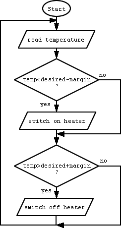
Write a program that reads the value of a temperature sensor and swithes a cooling motor on or off, according to the following flow chart. Possible applications are air conditioning, car radiator fan, or CPU cooling fan.
The program may be written in either assembly or C code. You will need to do the following things
Reading a temperature
Assembly - Use the following routine to read an analog value from a port (assuming the sensor is connected to port no. 6)
MOVE.L #6, D0 | pass channel no. in D0
JSR OS_GetAD | return result in D0The result is passed in D0 and is a value between 0 and 1023.
C - Call the following function
OSGetAD()
Switching the cooling motor off
MOVE.B #0, OutBase | switch motor off
Switching the cooling motor on
MOVE.B #1, OutBase | switch motor on
Parameters
desired temperature = 500
margin = 20
EXPERIMENT 2 - Motor Control
Servos are DC motors with built-in logic. They are e.g. used in model cars, airplanes, ships. Servos assume a position (often in the range of 360 degrees) according to an input rectangle signal.
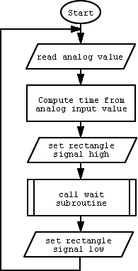
Write a program that reads an analog input value like in experiment 1 and then uses this value to generate a rectangle output on the digital output port. The servo should assume a position between its minimum and maximum position according to the analog input signal (potentiometer).
Example program segment:
MOVE.B #1, OutBase | switch rectangle signal on
MOVE.L time, D0 | pass wait time in 0.1ms in D0
JSR Wait01ms | wait D0 * 0.1 ms
MOVE.B #0, OutBase | switch rectangle signal offExample subroutine to wait D0 times 0.1 ms (input parameter D0):
Wait01ms: MULS.L #175, D0 | initialise loop
timeloop: SUB.L #1, D0 | use up time
BNE timeloop | loop until counter is 0
RTS
Servo control signal flowchart
Questions? Email Josh Petitt


