Digital & Embedded Systems
Tutorial 1: Arithmetic Logic Unit (ALU) Design
This tutorial is designed to help you learn the basics of ALU design.
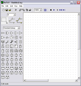
To complete this lab you will be using the simulation software ReTrO. This software allows the user to build and simulate circuit designs. You can learn more about ReTrO and download a copy here. When ReTrO is first opened, a window, like the one below, is displayed.
ReTrO default screen
To create a ReTrO model, click on one of the components in the left portion of the window, the tool palatte. Now move your cursor into the right portion of the window, the work area. Click anywhere in the work area to place the component.
To familiarise you with the operation of ReTrO, some examples are shown below. These examples show how ReTrO can be used to simulate the operation of some simple logic elements. To begin, we will now see how to assemble a RS flip-flop, a basic memory unit.
Making a RS flip-flop (a basic memory unit)
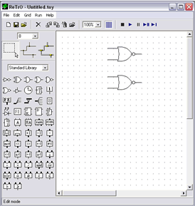
The RS flip-flop is a storage element with two stable states. By manipulating the two input values, one can set the flip-flop to a "high" state" or a "low state". The basic component the RS flip-flop is the NOR gate. Therefore to start the model, find the NOR gate symbol on the tool palette and place two onto the workspace.

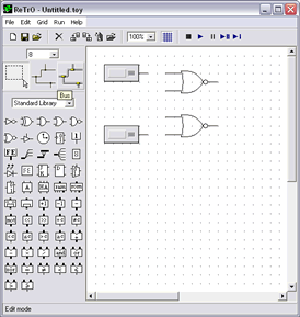
Now find the constant node component and place two of these on the work area.
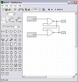
Next, place two LED components in the model. (Note, you will need to flip the LEDs horizontally. This can be done by right clicking on the component then selecting 'flip horizontal'.) Finally, connect the components with the 'wire' tool.
Perform the following set of steps on the RS flip-flop and watch the results.
Input
S R
Output value Qo
Apply 1 to R input and press the 'play button' 0 0 0 0 This is a stable state Apply 1 to S 0 1 0 1 Unstable state;Q changes
Qo becomes 1 1 1 0 1 Stable
Remove 1 from S 1 0 0 1 Stable state after SET Apply 1 to S again 1 1 0 1 No change in Q Remove 1 from S 1 0 0 1 Stable state after SET Apply 1 to R 1 0 1 0 Unstable state; Q changes Qo becomes 0 0 0 1 0 Stable Remove 1 from R 0 0 0 0 Stable state after RESET Apply 1 to both S and R 0 1 1 0 Unacceptable


